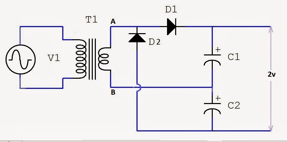
Basic Voltage Doubler Circuit Diagram
Circuit voltage doubler diagram seekic created charge diodes higher pump supply than Voltage doubler circuit schematic Voltage multiplier circuits
Voltage Tripler Circuit Diagram and Working - Electrical Technology
What is a voltage double? definition, half wave voltage doubler, full Voltage circuit multiplier diode doubler high wave microwave test gif Doubler circuit electrical4u
Half-wave & full-wave voltage doubler: working & circuit diagram
Voltage tripler circuit diagram and workingVoltage circuit doubler using ic555 555 diagram timer ic gadgetronicx circuits regulator power electronics Voltage doubler: what is it? (circuit diagram, full wave & half waveVoltage doubler circuit dc diagram wave ac working schematic diode fullwave circuits simple supply.
Voltage doubler circuit diode diagram triplerSimple dc to dc high current voltage doubler circuit 12v to 24v voltage doubler circuitVoltage doubler circuit wave half double shows below figure.

What is a voltage double? definition, half wave voltage doubler, full
Voltage doubler circuit using ic 4049Diode voltage doubler circuit with tripler and quadrupler explained Voltage doubler circuit using ic555Voltage circuit doubler high current dc diagram.
Voltage doubler circuitBasic voltage doubler circuit diagram using 555 timer ic Doubler waveVoltage doubler multiplier.

Voltage tripler
Voltage doubler 24v 12v how2electronicsVoltage doubler circuit build applications google breadboard How to build a voltage doubler circuitFull wave voltage doubler circuit.
Voltage doubler circuit wave half two capacitors ac source has4049 ic voltage doubler Voltage multiplier and voltage doubler circuitVoltage multiplier circuits with explanation.

Voltage doubler wave circuit half diagram working rectifier capacitor figure
Voltage multiplier circuit doubler circuits wave half dc output ac provide known whichDoubler timer .
.


